ZAAFIR HASAN

Airbrakes
Date
August 2021 - Present
Location
UC Berkeley
Role
Head Engineer
Project Type
Competition Team
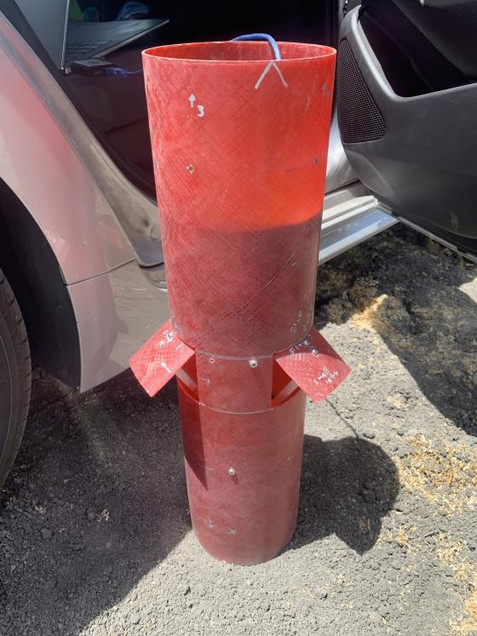
The airbrakes system utilizes a PID control loop to open and close flaps, inducing up to 12% increase in drag to achieve the target altitude. Materials include fiberglass, steel, aluminum, and 3D printed ABS with a total system weight of 7.4lbs. At maximum extension and velocity, the flaps can withstand 300lbs of force and open in 1.2 seconds.
The IREC competition requires rockets to reach a specific altitude(10k ft). STAR's solution uses airbrakes to intentionally overshoot the target and then slow down to hit it exactly. The design focuses on compactness, weight, and modularity to meet competition regulations and aerodynamics. The airbrakes system is designed to be modular, allowing for use on future competition rockets and easy replacement if damaged. It also allows for testing at more launch sites with FAA regulated altitude ceilings.
Design Constraints:
-
Fit into a 12in section of 6in diameter airframe
-
Maximum weight of 8lbs
-
Withstand the pressure of air at Mach .8 (max velocity)
-
The ability to slow the rocket down within the timespan from end of burn to apogee
-
The ability to have minimal effects on trajectory in event of failure
-
Factor of Safety of at least 1.5


The main mechanism is a COTS ballscrew that is cut to size. The arms and bulkheads are initially waterjetted and then drilled and tapped. The fiberglass is cut by hand using jigs.
The latest rendition of the airbrakes will have carbon fiber reinforced 3D printed arms and bulkheads, cutting 1.9lbs of weight


The Avionics Bay of our rocket design features a stepper motor, motor driver, Arduino microcontroller, altimeters, accelerometers, and batteries. While earlier prototypes were soldered together, the current version under development will be manufactured using a custom PCB. This design is engineered to withstand the harsh conditions of launch sites, including high temperatures and vibrations, and includes redundancies for failure mitigation.
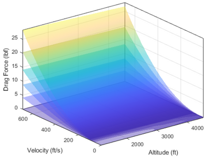
The live model uses PID control to optimize the flap extension based on altitude and velocity data, and utilizes a lookup table of drag values obtained through CFD analysis.
CFD Analysis was done using Ansys Fluent to analyze the drag on a model with five flap extensions: 0°, 10°, 20°, 30°, and 40°. The simulations were run at incremental altitudes, using a time dependent velocity simulation to get a smooth trend for drag. With these results, the live model has enough information to interpolate the drag at any point in time.
Additionally, wind tunnel testing was conducted to verify the concept of the airbrakes, using a miniature model with interchangeable fin sections. The results matched closely with our expected results for drag, providing validation for our data.


This is a poster I created to showcase our rocket design during a poster presentation session, aimed towards a panel of experts and recruiters.


